UAE Shops - Established in 2002
عربى


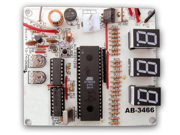
Microcontroller Based Bi Directional Visitor Counter
Visitor counting is simply a measurement of the visitor traffic entering and exiting offices, malls, sports venues, etc. Counting the visitors helps to maximize the efficiency and effectiveness of employees, floor area and sales potential of an organization. Visitor counting is not limited to the entry/exit point of a company but has a wide range of applications that provide information to management on the volume and flow of people throughout a location. The Microcontroller based Bi-directional Visitor Counter implemented here is a low-cost solution that can be used to count the number of persons entering a location. The Visitor Counter uses two IR transmitter-receiver pairs installed at the passage area: one pair comprising IR transmitter IR TX1 and receiver phototransistor T1 is installed at the entry point of the passage, while the other pair comprising IR transmitter IR TX2 and phototransistor T2 is installed at the exit of the passage. For the system to work, the signals from the IR LEDs should continuously fall on the respective phototransistors, i.e. proper orientation of the transmitters and phototransistors is necessary. The Microcontroller based Visitor Counter uses two similar sections that detect interruption of the IR beam and generate clock pulse for the microcontroller. The microcontroller controls the counting and displays the number of persons present inside the hall/room. The control logic is built around transistors, operational amplifier LM324 (IC1) and JK flip-flop (IC2). When nobody is passing through the entry/exit point, the IR beam continuously falls on phototransistor T1. Phototransistor T1 conducts and the high voltage at its emitter drives transistor T3 into saturation, which makes pin 3 of comparator N1 low and finally output pin 1 of comparator N1 is high. Now if someone enters the place, first the IR beam from IR TX1 is interrupted and then the IR beam from IR TX2. When the beam from IR TX1 is interrupted, phototransistor T1 and transistor T3 cut-off and pin 3 of comparator N1 goes high. The low output (pin 1) of comparator N1 provides negative trigger pulse to pin 1 of J-K flip-flop IC2 (A). At this moment, the high input at ‘J’ and ‘K’ pins of flip-flop IC2 (A) toggles its output to low. On the other hand, the low input at ‘J’ and ‘K’ pins of IC2 (B) due to clock pin 1 of IC2 (A) and ‘J’ input (pin 9) and ‘K’ input (pin 12) of IC2 (B) are connected to pin 1 of comparator N1. The negative-going pulse is applied to clock pin 6 of IC2 (B) when the person interrupts the IR beam from IR TX2. There is no change in the output of IC2 (B) flip-flop. This triggers the external interrupt INT0 (pin 12) of microcontroller AT89C52. Ports 0, 1 and 2 are configured for 7-segment displays. Port pins 3.0 and 3.1 are configured to provide the set pulse to J-K flip-flops IC2 (A) and IC2 (B), respectively. External interrupts INT0 and INT1 receive the interrupt pulse when the person interrupts the IR beams. Resistor R9 and capacitor C5 provide power-on-reset pulse to the microcontroller. Switch S1 is used for manual reset. When the microcontroller is reset, the flip-flops are brought in ‘set’ state through the microcontroller at software run time by making their ‘set’ pin high for a moment. The value of the counter gets incremented by ‘1’ when the interrupt service routine for INT0 is executed. The output of the corresponding J-K flip-flop is set to ‘high’ again by making its ‘set’ input pin low through the microcontroller. The micro-controller is configured as a negative- edge-triggered interrupt sensor. Similarly, if somebody exits the place, first the IR beam from IR TX2 is interrupted and then the IR beam from IR TX1. When the beam from IR TX2 is interrupted, output pin7 of comparator N2 goes low. This provides clock pulse to pin 6 of J-K flip-flop IC2 (B). At this moment, the high input at ‘J’ and ‘K’ pins of flip-flop IC2 (B) toggles its output to low. On the other hand, the low input at ‘J’ and ‘K’ pins of IC2 (A) due to clock pin 6 of IC2(B) and ‘J’ input (pin 4) and ‘K’ input (pin 16) of IC2 (A) are connected to pin 7 of comparator N2. The negative-going pulse is applied to clock pin 1 of IC2 (A) when the person interrupts the IR beam from IR TX1. There is no change in the output of IC2 (A) flip-flop. This triggers the external interrupt INT1 (pin 13) of microcontroller AT89C52. When the interrupt service routine for INT1 is executed once, the value of the counter decrements by ‘1’. The output of the corresponding J-K flip-flop is set to ‘high’ again by making its ‘set’ input pin low through the microcontroller. The circuit is powered by regulated 5V. The AC mains is stepped down by transformer X1 to deliver secondary output of 7.5V, 250mA, which is rectified by bridge rectifier BR1, filtered by capacitor C6 and regulated by IC 7805 (IC4). Capacitor C7 bypasses any ripple in the regulated output Learn : Learn interfacing of seven segment display with AT89C52. Learn application of IR transmittter and receiver using transistor 2N3904. Applciation of IC 74LS76.