UAE Shops - Established in 2002
عربى


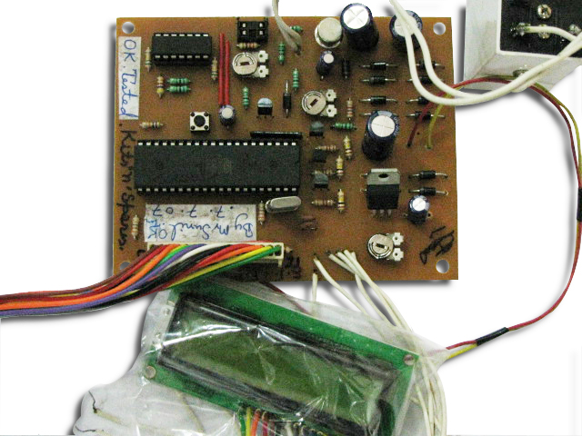
Micro controller Based Ultrasonic Distance Meter
This distance measurement for an object/obstruction is based upon the speed of sound at an ambient temperature of 25°C. The distance hence measured is displayed on a seven segment display for the user to read out. The micro-controller generates pulse bursts of 40 KHz at its pin3.4 which are amplified by transistor T5. The inverting buffer CD4049 drives the transmitter end of the ultrasonic transducer. Three inverters (N1, N2 and N3) are connected in parallel to increase the transmitted power. This inverted output is fed to another set of three inverters (N4, N5 and N6). Outputs of both sets of parallel inverters are applied as a push-pull drive to the ultrasonic transmitter. The positive-going pulse is applied to one of the terminals of the ultrasonic sensor and the same pulse after 180-degree phase shift is applied to the other terminal. Thus the transmitter power needs to be increased for increasing the range. The echo signal is received by the receiver sensor after reflection. This is a weak signal and is further amplified by quad op-amp IC LM324. The first stage (A1) is a buffer with unity gain. The received signal is directly fed to the non-inverting input (pin 3) of A1 and coupled to the second stage by a 3.3nF (small-value) capacitor. The second stage of the inverting amplifier uses a 2-mega-ohm resistor for feedback. The third stage is a precision rectifier amplifier with a gain of 10. The output (at pin8) from the LM324 IC is filtered by the rectifier diodes to accept 40 KHz frequencies and this signal is fed to pin12 (P1.0) of the micro-controller AT89C2051. This pin is the positive input (AIN0) terminal of the on-chip precision analog comparator, while pin13 (P1.1) serves as the negative input (AIN1) which is used for level adjustment using preset VR1. The ultrasonic transducer outputs a beam of sound waves, which has more energy on the main lobe and less energy (60 dB below the main lobe) on the side lobes as shown in Fig. 4. Even this low side-lobe signal is directly picked up by the receiver unit. Hence, it is important to space the transmitter and receiver units about 5cm apart. The echo signal will make port-3 pin 3.6 low when it goes above the level of voltage set on pin 13. This status is sensed by the micro-controller as programmed. When port-3 pin P3.6 goes high, we know that the echo signal has arrived; the timer is read and the 16-bit number is divided by twice the velocity of sound and then converted into decimal format as a 4-digit number. Note: To increase the range up to 5 meters, a ferrite-core step-up pulse transformer can be used, which steps-up the transmitter output to 60V (peak to peak). Learning: Learn the use of ultrasonic transmitter-receiver pair. Learn interfacing of AT89C2051 with ULN2003 and seven segment display. Use of quadruple operational amplifier IC LM324. Brand: Kits'n'spares, Marketed by: Kits'n'spares