UAE Shops - Established in 2002
عربى


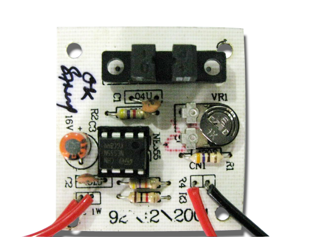
Smoke Alarm
Most smoke detecting circuits available commercially, make use of expensive smoke sensors which require complicated interfacing circuitry around them. However, the Smoke Alarm implemented here is capable of detecting smoke consistently and employs a simple phototransistor optical interrupter switch as the smoke sensor. This smoke-detecting circuit utilizes the simple fact that in case smoke is present, the optical signal transmitted from the infrared emitting diode to the photo-transistor (both part of the photo interrupter module) will be interrupted. Once such a situation is encountered, an alarm sound is generated by the loudspeaker till the time smoke clears. Number of ICs used: 1. The smoke alarm circuit employs a simple mechanism to detect smoke in the vicinity and sound an alarm. The sensing is done by the photo-transistor optical interrupter switch while the alarm is sounded by the NE555 timer IC, the output of the former acts as the input of the latter. In the absence of any smoke, the gap of the photo-transistor interrupter housing is clear and the infrared light from the diode falls directly onto the photo-transistor. This keeps the photo-transistor of the optical interrupter module in saturation. Owing to this, the reset pin (active LOW) of the NE555 IC is pulled to ground and it continuously resets the NE555 timer IC. No output is generated at pin3 and hence the loudspeaker does not sound an alarm. In case of smoke, the gap between the diode and the photo-transistor gets clouded with smoke and the optical signal is interrupted. (The threshold value of the least detectable smoke density is decided by the variable resistor VR1). This interruption in the optical signal causes the base voltage of photo-transistor to fall and cut-off. As a result, the collector terminal of the photo-transistor as well as the reset pin (pin no.4) of the NE555 IC is held high via resistor R2. Hence, oscillations are generated at the output pin (pin no.3) of the NE555, the frequency of which is decided by the value of R3, R4 and C1. This electrical signal (oscillations) is input to the loudspeaker through the capacitor C3 and is further converted into a loud and continuous alarm sound. Learning: Application of the phototransistor optical interrupter switch H21A1 Implementation of the astable mode of the NE555 timer IC. Brand: Kits'n'spares, Marketed by: Kits'n'spares