UAE Shops - Established in 2002
عربى


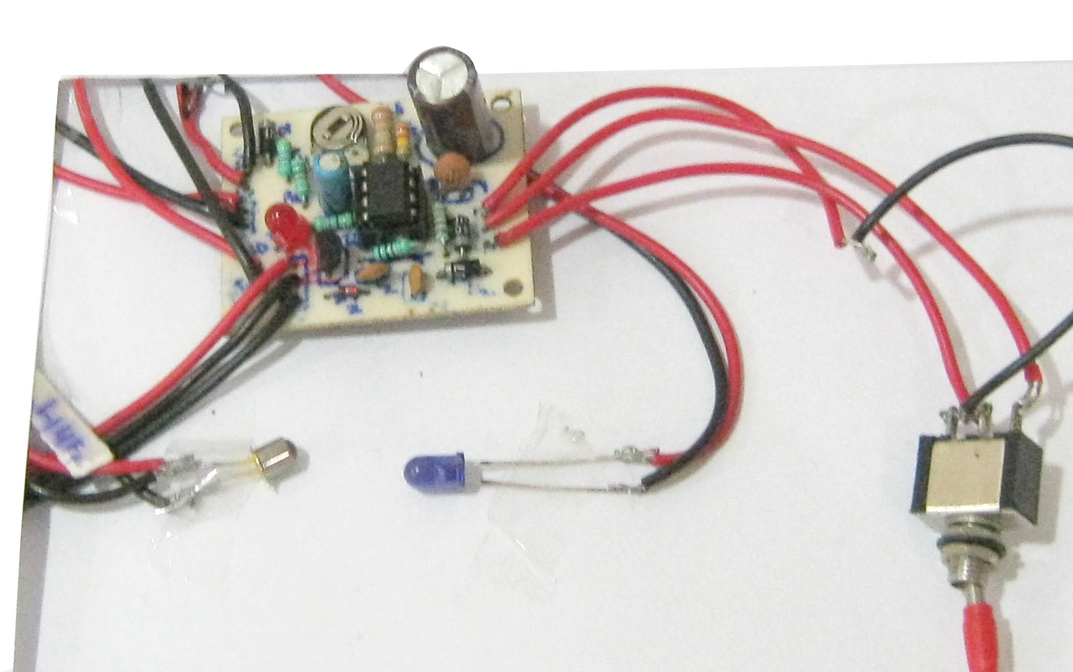
Smart Cellphone Holder
The Smart Cellphone Holder circuit makes sure that you do not forget to carry your mobile phone. The circuit is fitted inside the car and constantly searches for a mobile phone within the IR range of the circuit and alerts you through a flashing LED when it doesn’t find one. No. of ICs used: 1 The heart of the smart Cellphone Holder circuit is the timer IC LM555 (IC1) which derives power from the 12V DC automobile battery. When power is applied to the circuit, the low-frequency astable multivibrator built around IC1 is activated and a Red LED (LED2) at its output pin 3 flashes briefly. When the ignition switch (S2) of the car is flipped to ON position, the +12V DC from the car’s battery disables the astable multivibrator via a diode (D2) and LED2 turns off. When the ignition is turned off and the mobile phone is in its holder, LED2 again starts blinking. In case the cellphone holder is empty, IR rays from IR LED1 fall on photo-transistor 2N5777 (T1) and it conducts to pull the base of LED driver NPN transistor BC547 (T2) towards ground to disable the visual indicator (LED2). If you’ve forgotten to carry your cellphone, LED2 fitted in the cellphone holder will stop flashing to indicate that the mobile phone is not in the cell holder of the case. A variable resistor (VR1) determines the detection sensitivity of phototransistor T1. The blinking rate of LED2 can be changed by changing the value of capacitor C1 (or R3-R4 resistor combination) in the circuit. Learning: Application of the LM555 timer IC. Application of the 2N5777 phototransistor. Application of transistors for switching purposes. Brand: Kits'n'spares, Marketed by: Kits'n'spares