UAE Shops - Established in 2002
عربى


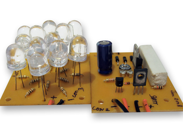
Automatic Low Power Emergency Light
The Automatic Low-Power Emergency Light is a white LED based emergency light that offers the following advantages: 1. It is extremely bright due to the use of white LEDs. 2. The light turns ON automatically when mains supply fails, and turns OFF when mains power resumes. 3. It has its own battery charger. When the battery is fully charged, charging stops automatically. No. of ICs used: 1 The circuit of the Automatic Low-Power Emergency Light comprises of two sections: Charger Power Supply and LED driver. The charger power supply section is built around the 3-terminal adjustable voltage regulator IC LM317 (IC1), while the LED driver section is built around the PNP transistor BD140 (T2). In the charger power supply section, input AC mains is stepped down by transformer X1 to deliver 9V, 500 mA to the bridge rectifier comprising of four diodes (D1 through D4). Filter capacitor (C1) eliminates ripples. Unregulated DC voltage is fed to input pin 3 of IC1 and provides charging current through a diode (D5) and a limiting resistor (R16). By adjusting the preset (VR1), the output voltage can be adjusted to deliver the required charging current. When the battery gets charged to 6.8V, zener diode (ZD1) conducts and charging current from regulator IC1 finds a path through the NPN transistor T1 (BC548) to ground and it stops charging of the battery. The LED driver section uses a total of twelve 10mm white LEDs. All the LEDs are connected in parallel with a 100-ohm resistor in series with each. The common-anode junction of all the twelve LEDs is connected to the collector of the PNP transistor BD140 (T2) and the emitter of this transistor is directly connected to the positive terminal of 6V battery. The unregulated DC voltage, produced at the cathode junction of diodes D1 and D3, is fed to the base of transistor T2 through a 1-kilo-ohm resistor. When mains power is available, the base of transistor T2 remains high and T2 does not conduct. Thus LEDs are off. On the other hand, when mains fails, the base of transistor T2 becomes low and it conducts. This makes all the LEDs (LED1 through LED12) glow. The mains power supply, when available, charges the battery and keeps the LEDs off as transistor T2 remains cut-off. During mains failure, the charging section stops working and the battery supply makes the LEDs glow. Learning: Application of the adjustable voltage regulator IC LM317. Application of Zener diodes for voltage regulation. Application of diodes in the bridge arrangement for rectification. Application of NPN and PNP transistors