UAE Shops - Established in 2002
عربى


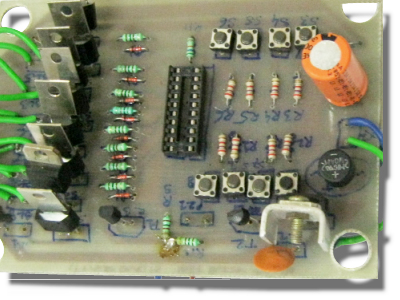
School College Quiz Buzzer
Manual buzzers used for quiz competitions in schools and colleges create a lot of confusion in identifying the first respondent. Although there are circuits using PCs and discrete ICs, they are either too expensive or limited to only a few number of players. The School/College Buzzer is a circuit that can be used for up to eight players.It uses the IC 74LS373 (which is an octal latch) and a few passive components to implement the quiz buzzer mechanism At the heart of the School/College Quiz Buzzer is the IC 74LS373 which transfers the logic state at data input pins (D0 through D7) to the corresponding outputs (Q0 through Q7). Data pins D0 through D7 are normally pulled low by resistors. One terminal of eight push-to-on switches (S1 through S8) is connected to +5V, while the other terminal is connected to the respective data input pins. The switches are to be extended to the players through cord wire. The torch bulbs (BL1 through BL8) can be housed in boxes with the front side of the boxes covered with a white paper having the name or number of the contestant written over it for easy identification. When the power is switched on using switch S9 (provided terminals ‘A’ and ‘B’ of both the power supply and quiz buzzer sections are interconnected), the circuit is ready to be used. Now all the switches (S1 through S8) are open and Q0 through Q7 outputs of IC 74LS373 (IC2) are low. As a result, the gates of silicon-controlled rectifiers (SCR1 through SCR8) are also low. As soon as a contestant momentarily presses his respective switch, the corresponding output data pin goes high. This triggers the corresponding SCR and the respective bulb glows. At the same time, the piezoelectric buzzer (PZ1) sounds as transistor BC548 (T1) conducts. Simultaneously, the base of transistor BC548 (T2) becomes high to make it conduct. Latch-enable (LE) pin 11 of IC2 is tied to ground to latch all the Q0 through Q7 outputs. This restricts further change in the output state due to any change in the state of switches S1 through S8 by any other contestant. Only one of the eight torch bulbs glows until the circuit is reset by on/off switch S9. Learning: Application of the octal latch IC 74LS3737. Use of SCRs in logic circuits. Application of transistors as switches Brand: Kits'n'spares, Marketed by: Kits'n'spares