UAE Shops - Established in 2002
عربى


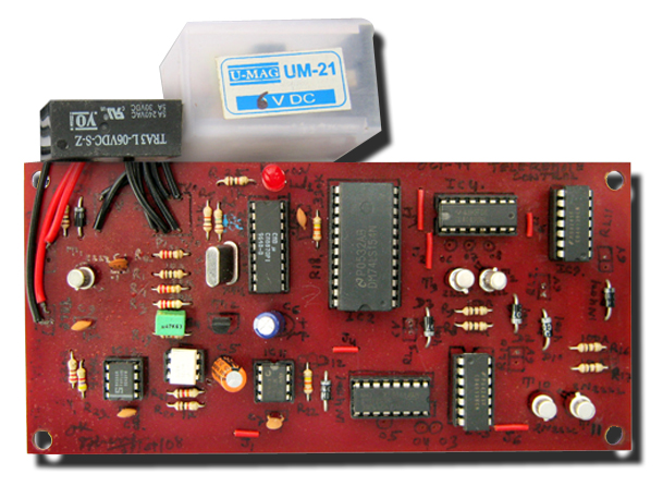
Teleremote Control
The Teleremote Control enables switching ‘on’ and ‘off’ of appliances through a telephone line. It can be used to switch appliances from any distance, overcoming the problem of limited range in infrared and radio remote control circuits. No. of ICs used: 8. The Teleremote control can be used to switch up to nine appliances (corresponding to the digits 1 through 9 on a telephone keypad). The DTMF signals of a telephone instrument are used as control signals. The digit ‘0’ in the DTMF mode is used to toggle between the appliance mode and the normal telephone operation mode. Thus the telephone can be used to switch on or switch off the appliances while also being used for a telephonic conversation. The circuit uses IC KT3170 (DTMF-to-BCD converter or IC1), 74154 (4-to-16-line de-multiplexer or IC2), and five CD4013 (D flip-flop) ICs. Once a call is established (after hearing ring-back tone), a ‘0’ is dialed in the DTMF mode. IC1 decodes this as ‘1010,’ which is further demultiplexed by IC2 as output O10 (at pin 11) of IC2 (74154). The active low output of IC2, after inversion by an inverter gate of IC3 (CD4049), becomes logic 1. This is used to toggle flip-flop-1 (F/F-1) and relay RL1 is energised. Relay RL1 has two changeover contacts, RL1(a) and RL1(b). The energised RL1(a) contacts provide a 220-ohm loop across the telephone line while RL1(b) contacts inject a 10kHz tone on the line, which indicates to the caller that appliance mode has been selected. The 220-ohm loop on telephone line disconnects the ringer from the telephone line in the exchange. The line is now connected for appliance mode of operation. If digit ‘0’ is not dialed (in DTMF) after establishing the call, the ring continues and the telephone can be used for normal conversation. After selection of the appliance mode of operation, if digit ‘1’ is dialed, it is decoded by IC1 and its output is ‘0001’. This BCD code is then de-multiplexed by the de-multiplexer (IC2) whose corresponding output, after inversion by a CD4049 inverter gate, goes to logic 1 state. This pulse toggles the corresponding flip-flop to alternate state. The flip-flop output is used to drive a relay (RL2) which can switch on or switch off the appliance connected through its contacts. By dialing other digits in a similar way, other appliances can also be switched ‘on’ or ‘off.’ Once the switching operation is over, the 220-ohm loop resistance and 10kHz tone needs to be removed from the telephone line. To achieve this, digit ‘0’ (in DTMF mode) is dialed again to toggle flip-flop-1 to de-energize relay RL1, which terminates the loop on line and the 10kHz tone is also disconnected. The telephone line is thus again set free to receive normal calls. This circuit is to be connected in parallel to the telephone instrument. Learning: Application of the DTMF-to-BCD converter IC KT3170 Application and use of de-multiplexer and the concept of demultiplexing Application of D flip-flops in logic circuits Brand: Kits'n'spares, Marketed by: Kits'n'spares