UAE Shops - Established in 2002
عربى


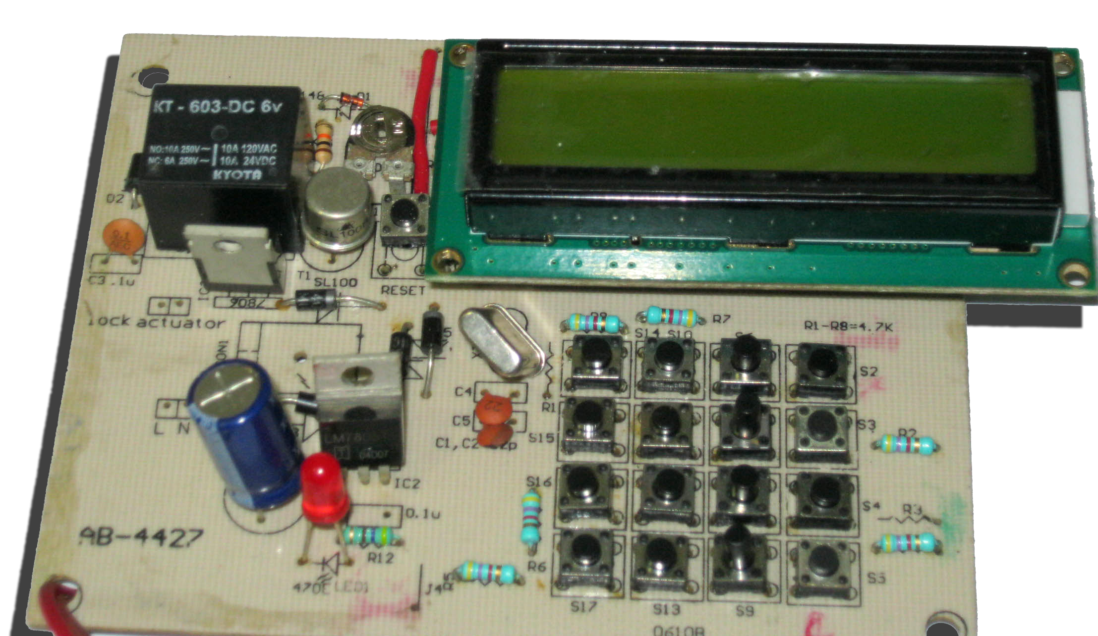
PIC Microcontroller Based Electronic Lock
A electronic lock allows only a authorized entry to your home/office/car. This circuit comprises of a PIC16F877A MCU which plays role of processing unit. It is interfaced with a 4×4 matrix keypad for entering password and a 16×2 LCD for display. When a correct password is pressed it energies the relay and lock is opened. The circuit is based on PIC micro controller. It can be divided into five sections: input(4×4 matrix keypad), processing unit (PIC16F877A MCU), appliance controller (relay driver), display (16×2 LCD), and power supply. PIC16F877A MCU. The PIC-16F877A is an 8-bit micro controller . It has 8k×14-bit flash program memory, 368 bytes of RAM and many other internal peripherals like analogue-to-digital converter, USART, timers, synchronous serial port, compare captures and pulse width modulation modules, EEPROM and analogue comparators. The job of the MCU in this project is to receive signals from the input device (keypad) and take corresponding actions. Whenever any key is pressed on the keypad, the software program in the MCU identifies the pressed key and accordingly turns on or turns off the appliance. Simultaneously, it also displays a message on the LCD screen. 4×4 matrix keypad. A 4×4 matrix keypad is used to give commands and the password to the MCU. It consists of 16 keys (S2-S17) arranged in the form of a square matrix of four rows and four columns. Each key in the matrix is labeled according to the operation assigned to it. 16×2 LCD. A Hitachi HD44780 16×2 LCD is used to display various messages. It also displays an asterisk mark (*) for each digit of the password entered. Control lines EN, RW and RS of the LCD module are connected to pins RA1, RA2 and RA3 of Port A of the MCU, respectively. Commands and the data to be displayed are sent to the LCD module in nibble mode from Port D of the MCU. The higher four data bits of the LCD (D4 through D7) are connected to the lower nibble of Port D (RD0 through RD3) of the MCU. Relay driver. RC2 pin of Port C of the MCU is interfaced with the relay driver circuit to switch on or switch off the AC load (appliance). A relay driver circuit is nothing but a simple electronic circuit that drives an electromechanical relay. In this project, a 6V, single-changeover relay is used for switching the appliance ‘on’ or ‘off.’ Transistor SL100 plays the role of the relay driver. Whenever the user enters the correct password, RC2 pin goes high . Consequently, transistor SL100 is triggered to energies the relay and the appliance turns‘on.’ When RC2 is low , the appliance turns ‘off.’Free-wheeling diode 1N4007 protects the relay driver circuit from the reverse voltage developed in the relay coil. Power supply. Fig. 2 shows the power supply circuit. The 230V AC mains supply is stepped down to 9V AC using step-down transformer X1. The output from the secondary of the transformer is rectified by a bridge rectifier comprising diodes D3 through D6 and filtered by capacitor C1. The filtered output is regulated by ICs 7805 and 7806 connected in parallel to obtain the required 5V and 6V, respectively. Brand: Kits'n'spares, Marketed by: Kits'n'spares